As usual, one thing distracts another. The hardware is set up for the first VGA test, but the code has not come out yet. In the meantime, I found an old LCD screen that I wanted to examine. It comes from an old DVD player for the car. The main unit has a DVD player and 7" LCD screen. It also comes with a second 7" LCD that attaches to the main unit via a three prong RCA cable. The signal should be composite video. The screen on the main player is broken, but the second one works. It is small, thin, and portable.
It is ripe for hacking, so VGA will now have to wait. This screen is just waiting for a game of Pong or just a cool, big, text terminal! The NTSC and PAL standards are quite taxing to implement in software. Questions to the Google revealed a few possible shortcuts. Here then are my notes thus far. The project will attempt to write black and white ( and maybe some gray ), using my new Pic18F4550, clocked with PLL at 48MHz. This gives a Pic a working speed of 12 MIPS. The links below provide some of the shortcuts that should make the vertical synching less of a hassle.
==========================
Composite Video
==========================
-------------
17 May, 2012
-------------
References
----------
Rikard Gunee's Pong and Tetris on a Pic
The Post That Gave Me Inspiration
Uzebox
The Shortcuts from AVRFreaks
Going to try the simplest method. This will not try to do interlaced lines. Instead, it will only do the even line field over and over.
Frame = 2 fields of both even lines.
Timings
--------
Line = 63.5 us
262 lines per field
Time per Field = 262 x 63.5 = 16.637 ms
Line Parts
----------
Name Voltage Time Instructions @ 12 Mips
_______________________________________________________
Front Porch .3V 1.4us 17 ( actual 16.8 )
HSynch 0V 4.4us 53 ( actual 52.8 )
Back Porch .3V 4.4us 53 ( actual 52.8 )
Active .3-1.2V 53.3us 639 ( actual 639.6 )
Total Instructions = 762
Freq = 8.333 x 10^-8
Total Time = 762 x 8.333x10^-8 = 63.5us
Vertical Synch
---------------
Try just setting the line to 0V for the whole 63.5us on the 3 VSynch lines.
Field Layout
------------
Lines Function
------------------------------------
3 Dummy H lines
3 VSynch lines
14 Dummy H lines
242 Visible lines
Dummy H line:
Front Porch, HSynch, Back Porch, .3V for active 53.3us
During the active time of the dummy lines, 639 free instructions are available per line.
Use this time to set up the line arrays.
Pin Setup
----------
Pin 1 has a 470 Ohm resistor
Pin 0 has a 1k resistor
Pins Result
---------------
00 0V (synch)
01 .3V (black)
10 .6V (gray)
11 1V (white)
Interrupts
-----------
Use Timer 0 in 16 bit mode. Interrupt every 63.5us ( every 762 instructions at 48MHz ).
65536 - 762 = 64774
In binary = 0b1111110100000110
The High byte is 253
The Low byte is 6
High = 0xFD
Low = 0x06
Need to keep track of line numbers. At start of interrupt, immediately set output to 01 ( black ).
If it is a vertical synch, set output port to 00 ( 0V ) and return to process data.
Else, waste time and do the horizontal synch ( porches and synch ).
If it's a dummy line, return to main for processing.
If it's an active line, process the line.
Need to figure out the line and array housekeeping, too.
Need to look for a way to use the 106 instructions of porch and Hsynch time effectively.
Thursday, May 17, 2012
Sunday, May 6, 2012
VGA Wiring, Fast 16 Bit Counters
Here are a few brief notes/findings.
Cheap Wire
Home Depot in the States sells Cat 5e riser network cable. This is 24 AWG solid core wire. There are 8 wires in the cable. These work fairly well as jumper wires for breadboard. Left in the insulator, they make really good connection wires. There are eight of them, so that's a parallel byte or a full register. In the case of the line follower I want, that's the six input lines and the power and ground. One short of what is needed ( the LED on/off line ). Here's the cool part: THE PRICE! A 20 foot roll of a single wire at 22 AWG at Radio Shack is a bit over $8.00 USD. The Cat 5e Riser ( not Plenum ) cable is $0.18 per foot. And that's for eight wires. The stuff can be used like Kleenex at that price. Plenum cable is not much more expensive at about $0.59 per foot. This stuff is going on almost everything project from now on.
VGA
A VGA driver is the next experiment on the docket. Lucid Science has a great tutorial. It's written for an Atmel AVR in assembly. With a datasheet and maybe a tutorial, it's pretty easy to adapt to a PIC. The main problem with the PIC is speed. Even with an 18F microcontroller running at 96 MHz with PLL, the processor gets 48 MHz from that. Each instruction takes four clocks, so the effective MIPS is 12. This is slow and it makes conversion a bit tricky. It should be possible to get a test display of Lucid Science's RRGGBBII palette to work. Even with SRAM, the operable resolution for graphics will be pretty low, though. Still, it should be fun to try.
To that end, I wired up a VGA female cable, using some newly purchased Cat 5e cable. As a reminder to myself:
Fast 16 Bit Counter
Now for some cool news. The 18F series has made some big improvements. First, you can avoid the Read-Modify-Write problem by writing directly to the Latch registers for the ports. Next, they include a new SFR, WREG. This shadows the W register. Unlike the W register, it allows direct math and manipulation. Mathematical operations on the WREG can be interchanged with W reserved operations like movlw and addwf.
Tonight proved two other operations unknown to me. First, it is possible to maintain a 16 Bit increment ( an increment over 2 bytes ) in only 2 instructions. The W register must be zero for this to work. The lower byte is incremented as usual with incf:
movlw 0x000
incf myRegLow,F
Then, the magical addwfc is invoked. This adds the W register ( value zero ) to the higher byte as well as the Carry bit from the last operation ( the incf ). This effectively increments the higher byte only when the lower byte overflows to 256 ( ie, back to zero ).
addwfc myRegHigh,F
Wait, wait. Don't order yet! Now how much would you pay? If you act now, we'll throw in the fact that you can do mathematical operations directly on the Latch registers! This means that if the SRAM address for VGA output needs to be incremented very quickly through 16 bits worth of addresses ( and it does ), it is possible. If LATB holds the lower address byte and LATD holds the higher byte:
movlw 0x000
beginAddressLoop:
incf LATB,F
addwfc LATD,F
bra beginAddressLoop
This, of course, is nothing like what will be used. It does illustrate the point. These little discoveries will drastically reduce the cycles needed for the various operations needed for VGA output.
Cheap Wire
Home Depot in the States sells Cat 5e riser network cable. This is 24 AWG solid core wire. There are 8 wires in the cable. These work fairly well as jumper wires for breadboard. Left in the insulator, they make really good connection wires. There are eight of them, so that's a parallel byte or a full register. In the case of the line follower I want, that's the six input lines and the power and ground. One short of what is needed ( the LED on/off line ). Here's the cool part: THE PRICE! A 20 foot roll of a single wire at 22 AWG at Radio Shack is a bit over $8.00 USD. The Cat 5e Riser ( not Plenum ) cable is $0.18 per foot. And that's for eight wires. The stuff can be used like Kleenex at that price. Plenum cable is not much more expensive at about $0.59 per foot. This stuff is going on almost everything project from now on.
VGA
A VGA driver is the next experiment on the docket. Lucid Science has a great tutorial. It's written for an Atmel AVR in assembly. With a datasheet and maybe a tutorial, it's pretty easy to adapt to a PIC. The main problem with the PIC is speed. Even with an 18F microcontroller running at 96 MHz with PLL, the processor gets 48 MHz from that. Each instruction takes four clocks, so the effective MIPS is 12. This is slow and it makes conversion a bit tricky. It should be possible to get a test display of Lucid Science's RRGGBBII palette to work. Even with SRAM, the operable resolution for graphics will be pretty low, though. Still, it should be fun to try.
To that end, I wired up a VGA female cable, using some newly purchased Cat 5e cable. As a reminder to myself:
| Pin | Wire Color(s) | Value |
|---|---|---|
| 1 | Orange | Red |
| 2 | Green | Green |
| 3 | Blue | Blue |
| 5,6,7,8,10 | White/Green White/Blue White/Orange |
Ground |
| 13 | Brown | Hz Synch |
| 14 | White/Brown | Vt Synch |
Fast 16 Bit Counter
Now for some cool news. The 18F series has made some big improvements. First, you can avoid the Read-Modify-Write problem by writing directly to the Latch registers for the ports. Next, they include a new SFR, WREG. This shadows the W register. Unlike the W register, it allows direct math and manipulation. Mathematical operations on the WREG can be interchanged with W reserved operations like movlw and addwf.
Tonight proved two other operations unknown to me. First, it is possible to maintain a 16 Bit increment ( an increment over 2 bytes ) in only 2 instructions. The W register must be zero for this to work. The lower byte is incremented as usual with incf:
movlw 0x000
incf myRegLow,F
Then, the magical addwfc is invoked. This adds the W register ( value zero ) to the higher byte as well as the Carry bit from the last operation ( the incf ). This effectively increments the higher byte only when the lower byte overflows to 256 ( ie, back to zero ).
addwfc myRegHigh,F
Wait, wait. Don't order yet! Now how much would you pay? If you act now, we'll throw in the fact that you can do mathematical operations directly on the Latch registers! This means that if the SRAM address for VGA output needs to be incremented very quickly through 16 bits worth of addresses ( and it does ), it is possible. If LATB holds the lower address byte and LATD holds the higher byte:
movlw 0x000
beginAddressLoop:
incf LATB,F
addwfc LATD,F
bra beginAddressLoop
This, of course, is nothing like what will be used. It does illustrate the point. These little discoveries will drastically reduce the cycles needed for the various operations needed for VGA output.
Friday, May 4, 2012
Hand Made Board - Finished!
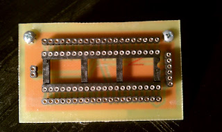
The Dremel drill bits from Amazon arrived. They come in a packet of 4 and are 1/32". Man, are they small! They fit in the Dremel chuck nicely, but it took a bit of fiddling to get them in straight. The problem with the Dremel is that the hold button needs to be depressed as you tighten. The whole operation would be a lot easier with three hands. I used my trusty Dremel drill press and banged out the holes. It was very easy. I took my time. The copper around the holes actually nudge the bit where it needs to go. The Dremel was set to 15,000 RPMs. The bit dwells a bit at the top of the cut, then a smooth plunge finishes off each hole. Here's the result:

Soldering was very different from either a proto-board or a professional PCB. The solder and heat want to go everywhere. The ground plane was particularly a problem. I have to admit, I rushed the soldering. I was so excited that everything looked good. I just wanted to see the board done. Here's the top with the pins and sockets added:
Here's a picture of the bottom solder that's as bad as the soldering job:

I printed out a pin "cheat sheet" for the microcontroller in lieu of a stencil:

Now, to test it out with a hello world style blinking LED!

Soldering was very different from either a proto-board or a professional PCB. The solder and heat want to go everywhere. The ground plane was particularly a problem. I have to admit, I rushed the soldering. I was so excited that everything looked good. I just wanted to see the board done. Here's the top with the pins and sockets added:

Here's a picture of the bottom solder that's as bad as the soldering job:

I printed out a pin "cheat sheet" for the microcontroller in lieu of a stencil:

Now, to test it out with a hello world style blinking LED!
Subscribe to:
Posts (Atom)