I've been playing around with MPLAB X lately. It's still quite buggy, but I love the convenience of an IDE that manages my code, lets me version the software, program the devices, step debug, etc. It's a shame they chose NetBeans instead of Eclipse. Regardless, some new learnings were in the offing. I wrote some programs in C with Microchips C18 compiler. I learned how to program the chips for In Circuit Debugging (ICD ) with the PicKit2. Wow! It is definitely cool to be able to step debug on the actual circuit.
Not much to show for this first foray. I redid an old routine that reads from the ADC on AN0 and pushes the value onto an LCD screen. The set up and whatnot is the same as posted in earlier blogs. The difference was porting the whole thing to C. The config fuses are set in an include file to get them out of the way. Here it is:
configFuses.h
The source code is fairly compact:
adc_lcd.c
Next up is a hybrid C and assembly program that I've been wanting to do. It reads an analog value from AN0. I took advantage of C to divide the value by 6 and add one. This result is fed to a servo value. The servo is driven by chained interrupts on timers 0 and 1. Timer 0 acts as the controller and interrupts on the period ( 50 Hz or 20ms ). On interrupt, it resets itself and starts timer 1 for the first .65 ms of the duty cycle. It turns on all servos ( in this case only one ). The timer 1 interrupt handles the remaining 1.35 ms of the duty cycle. It sets itself to interrupt every 7.4 us for 180 times. This means that the servos will have a resolution of 180 degrees.
The interrupts are all written in assembly. While they could have been done in C for one servo, this code wants to evolve to control 16 or 17 servos at a time. Each will have an independent value. To control the 18 or more servos for a hexapod, the timings will have to adjust to a PLL driven clock at 48 MHz. That buys 160 instructions per "degree" of resolution to work with ( as opposed to the 40 instructions available at 20 MHz ).
The assembly portion is rammed into the code inline. This led to some interesting knowledge. The program employs a lot of #define statements to make the code more readable and adjustable. All of the delays and interrupt timings are done by define. It should be a simple matter to adjust them to 48 MHz. For the assembly, the pins needed to be defined as well. They could not use the definitions from the chip's include file. As a part of changing the timings for 48 MHz, the assembly will be placed in its own .asm file and linked in. That should simplify things.
The same configFuses.h file was used as above. One thing to note: The MCLR is ON in this file. This allows debugging the program in circuit. It also means a 10k resistor needs to be connected to RE3.
Here is the code for the servo tester as it stands now: adc_servo.c
That's all for now!
Sunday, July 29, 2012


Thursday, May 17, 2012
NTSC Composite Video
As usual, one thing distracts another. The hardware is set up for the first VGA test, but the code has not come out yet. In the meantime, I found an old LCD screen that I wanted to examine. It comes from an old DVD player for the car. The main unit has a DVD player and 7" LCD screen. It also comes with a second 7" LCD that attaches to the main unit via a three prong RCA cable. The signal should be composite video. The screen on the main player is broken, but the second one works. It is small, thin, and portable.
It is ripe for hacking, so VGA will now have to wait. This screen is just waiting for a game of Pong or just a cool, big, text terminal! The NTSC and PAL standards are quite taxing to implement in software. Questions to the Google revealed a few possible shortcuts. Here then are my notes thus far. The project will attempt to write black and white ( and maybe some gray ), using my new Pic18F4550, clocked with PLL at 48MHz. This gives a Pic a working speed of 12 MIPS. The links below provide some of the shortcuts that should make the vertical synching less of a hassle.
==========================
Composite Video
==========================
-------------
17 May, 2012
-------------
References
----------
Rikard Gunee's Pong and Tetris on a Pic
The Post That Gave Me Inspiration
Uzebox
The Shortcuts from AVRFreaks
Going to try the simplest method. This will not try to do interlaced lines. Instead, it will only do the even line field over and over.
Frame = 2 fields of both even lines.
Timings
--------
Line = 63.5 us
262 lines per field
Time per Field = 262 x 63.5 = 16.637 ms
Line Parts
----------
Name Voltage Time Instructions @ 12 Mips
_______________________________________________________
Front Porch .3V 1.4us 17 ( actual 16.8 )
HSynch 0V 4.4us 53 ( actual 52.8 )
Back Porch .3V 4.4us 53 ( actual 52.8 )
Active .3-1.2V 53.3us 639 ( actual 639.6 )
Total Instructions = 762
Freq = 8.333 x 10^-8
Total Time = 762 x 8.333x10^-8 = 63.5us
Vertical Synch
---------------
Try just setting the line to 0V for the whole 63.5us on the 3 VSynch lines.
Field Layout
------------
Lines Function
------------------------------------
3 Dummy H lines
3 VSynch lines
14 Dummy H lines
242 Visible lines
Dummy H line:
Front Porch, HSynch, Back Porch, .3V for active 53.3us
During the active time of the dummy lines, 639 free instructions are available per line.
Use this time to set up the line arrays.
Pin Setup
----------
Pin 1 has a 470 Ohm resistor
Pin 0 has a 1k resistor
Pins Result
---------------
00 0V (synch)
01 .3V (black)
10 .6V (gray)
11 1V (white)
Interrupts
-----------
Use Timer 0 in 16 bit mode. Interrupt every 63.5us ( every 762 instructions at 48MHz ).
65536 - 762 = 64774
In binary = 0b1111110100000110
The High byte is 253
The Low byte is 6
High = 0xFD
Low = 0x06
Need to keep track of line numbers. At start of interrupt, immediately set output to 01 ( black ).
If it is a vertical synch, set output port to 00 ( 0V ) and return to process data.
Else, waste time and do the horizontal synch ( porches and synch ).
If it's a dummy line, return to main for processing.
If it's an active line, process the line.
Need to figure out the line and array housekeeping, too.
Need to look for a way to use the 106 instructions of porch and Hsynch time effectively.
It is ripe for hacking, so VGA will now have to wait. This screen is just waiting for a game of Pong or just a cool, big, text terminal! The NTSC and PAL standards are quite taxing to implement in software. Questions to the Google revealed a few possible shortcuts. Here then are my notes thus far. The project will attempt to write black and white ( and maybe some gray ), using my new Pic18F4550, clocked with PLL at 48MHz. This gives a Pic a working speed of 12 MIPS. The links below provide some of the shortcuts that should make the vertical synching less of a hassle.
==========================
Composite Video
==========================
-------------
17 May, 2012
-------------
References
----------
Rikard Gunee's Pong and Tetris on a Pic
The Post That Gave Me Inspiration
Uzebox
The Shortcuts from AVRFreaks
Going to try the simplest method. This will not try to do interlaced lines. Instead, it will only do the even line field over and over.
Frame = 2 fields of both even lines.
Timings
--------
Line = 63.5 us
262 lines per field
Time per Field = 262 x 63.5 = 16.637 ms
Line Parts
----------
Name Voltage Time Instructions @ 12 Mips
_______________________________________________________
Front Porch .3V 1.4us 17 ( actual 16.8 )
HSynch 0V 4.4us 53 ( actual 52.8 )
Back Porch .3V 4.4us 53 ( actual 52.8 )
Active .3-1.2V 53.3us 639 ( actual 639.6 )
Total Instructions = 762
Freq = 8.333 x 10^-8
Total Time = 762 x 8.333x10^-8 = 63.5us
Vertical Synch
---------------
Try just setting the line to 0V for the whole 63.5us on the 3 VSynch lines.
Field Layout
------------
Lines Function
------------------------------------
3 Dummy H lines
3 VSynch lines
14 Dummy H lines
242 Visible lines
Dummy H line:
Front Porch, HSynch, Back Porch, .3V for active 53.3us
During the active time of the dummy lines, 639 free instructions are available per line.
Use this time to set up the line arrays.
Pin Setup
----------
Pin 1 has a 470 Ohm resistor
Pin 0 has a 1k resistor
Pins Result
---------------
00 0V (synch)
01 .3V (black)
10 .6V (gray)
11 1V (white)
Interrupts
-----------
Use Timer 0 in 16 bit mode. Interrupt every 63.5us ( every 762 instructions at 48MHz ).
65536 - 762 = 64774
In binary = 0b1111110100000110
The High byte is 253
The Low byte is 6
High = 0xFD
Low = 0x06
Need to keep track of line numbers. At start of interrupt, immediately set output to 01 ( black ).
If it is a vertical synch, set output port to 00 ( 0V ) and return to process data.
Else, waste time and do the horizontal synch ( porches and synch ).
If it's a dummy line, return to main for processing.
If it's an active line, process the line.
Need to figure out the line and array housekeeping, too.
Need to look for a way to use the 106 instructions of porch and Hsynch time effectively.
Sunday, May 6, 2012
VGA Wiring, Fast 16 Bit Counters
Here are a few brief notes/findings.
Cheap Wire
Home Depot in the States sells Cat 5e riser network cable. This is 24 AWG solid core wire. There are 8 wires in the cable. These work fairly well as jumper wires for breadboard. Left in the insulator, they make really good connection wires. There are eight of them, so that's a parallel byte or a full register. In the case of the line follower I want, that's the six input lines and the power and ground. One short of what is needed ( the LED on/off line ). Here's the cool part: THE PRICE! A 20 foot roll of a single wire at 22 AWG at Radio Shack is a bit over $8.00 USD. The Cat 5e Riser ( not Plenum ) cable is $0.18 per foot. And that's for eight wires. The stuff can be used like Kleenex at that price. Plenum cable is not much more expensive at about $0.59 per foot. This stuff is going on almost everything project from now on.
VGA
A VGA driver is the next experiment on the docket. Lucid Science has a great tutorial. It's written for an Atmel AVR in assembly. With a datasheet and maybe a tutorial, it's pretty easy to adapt to a PIC. The main problem with the PIC is speed. Even with an 18F microcontroller running at 96 MHz with PLL, the processor gets 48 MHz from that. Each instruction takes four clocks, so the effective MIPS is 12. This is slow and it makes conversion a bit tricky. It should be possible to get a test display of Lucid Science's RRGGBBII palette to work. Even with SRAM, the operable resolution for graphics will be pretty low, though. Still, it should be fun to try.
To that end, I wired up a VGA female cable, using some newly purchased Cat 5e cable. As a reminder to myself:
Fast 16 Bit Counter
Now for some cool news. The 18F series has made some big improvements. First, you can avoid the Read-Modify-Write problem by writing directly to the Latch registers for the ports. Next, they include a new SFR, WREG. This shadows the W register. Unlike the W register, it allows direct math and manipulation. Mathematical operations on the WREG can be interchanged with W reserved operations like movlw and addwf.
Tonight proved two other operations unknown to me. First, it is possible to maintain a 16 Bit increment ( an increment over 2 bytes ) in only 2 instructions. The W register must be zero for this to work. The lower byte is incremented as usual with incf:
movlw 0x000
incf myRegLow,F
Then, the magical addwfc is invoked. This adds the W register ( value zero ) to the higher byte as well as the Carry bit from the last operation ( the incf ). This effectively increments the higher byte only when the lower byte overflows to 256 ( ie, back to zero ).
addwfc myRegHigh,F
Wait, wait. Don't order yet! Now how much would you pay? If you act now, we'll throw in the fact that you can do mathematical operations directly on the Latch registers! This means that if the SRAM address for VGA output needs to be incremented very quickly through 16 bits worth of addresses ( and it does ), it is possible. If LATB holds the lower address byte and LATD holds the higher byte:
movlw 0x000
beginAddressLoop:
incf LATB,F
addwfc LATD,F
bra beginAddressLoop
This, of course, is nothing like what will be used. It does illustrate the point. These little discoveries will drastically reduce the cycles needed for the various operations needed for VGA output.
Cheap Wire
Home Depot in the States sells Cat 5e riser network cable. This is 24 AWG solid core wire. There are 8 wires in the cable. These work fairly well as jumper wires for breadboard. Left in the insulator, they make really good connection wires. There are eight of them, so that's a parallel byte or a full register. In the case of the line follower I want, that's the six input lines and the power and ground. One short of what is needed ( the LED on/off line ). Here's the cool part: THE PRICE! A 20 foot roll of a single wire at 22 AWG at Radio Shack is a bit over $8.00 USD. The Cat 5e Riser ( not Plenum ) cable is $0.18 per foot. And that's for eight wires. The stuff can be used like Kleenex at that price. Plenum cable is not much more expensive at about $0.59 per foot. This stuff is going on almost everything project from now on.
VGA
A VGA driver is the next experiment on the docket. Lucid Science has a great tutorial. It's written for an Atmel AVR in assembly. With a datasheet and maybe a tutorial, it's pretty easy to adapt to a PIC. The main problem with the PIC is speed. Even with an 18F microcontroller running at 96 MHz with PLL, the processor gets 48 MHz from that. Each instruction takes four clocks, so the effective MIPS is 12. This is slow and it makes conversion a bit tricky. It should be possible to get a test display of Lucid Science's RRGGBBII palette to work. Even with SRAM, the operable resolution for graphics will be pretty low, though. Still, it should be fun to try.
To that end, I wired up a VGA female cable, using some newly purchased Cat 5e cable. As a reminder to myself:
| Pin | Wire Color(s) | Value |
|---|---|---|
| 1 | Orange | Red |
| 2 | Green | Green |
| 3 | Blue | Blue |
| 5,6,7,8,10 | White/Green White/Blue White/Orange |
Ground |
| 13 | Brown | Hz Synch |
| 14 | White/Brown | Vt Synch |
Fast 16 Bit Counter
Now for some cool news. The 18F series has made some big improvements. First, you can avoid the Read-Modify-Write problem by writing directly to the Latch registers for the ports. Next, they include a new SFR, WREG. This shadows the W register. Unlike the W register, it allows direct math and manipulation. Mathematical operations on the WREG can be interchanged with W reserved operations like movlw and addwf.
Tonight proved two other operations unknown to me. First, it is possible to maintain a 16 Bit increment ( an increment over 2 bytes ) in only 2 instructions. The W register must be zero for this to work. The lower byte is incremented as usual with incf:
movlw 0x000
incf myRegLow,F
Then, the magical addwfc is invoked. This adds the W register ( value zero ) to the higher byte as well as the Carry bit from the last operation ( the incf ). This effectively increments the higher byte only when the lower byte overflows to 256 ( ie, back to zero ).
addwfc myRegHigh,F
Wait, wait. Don't order yet! Now how much would you pay? If you act now, we'll throw in the fact that you can do mathematical operations directly on the Latch registers! This means that if the SRAM address for VGA output needs to be incremented very quickly through 16 bits worth of addresses ( and it does ), it is possible. If LATB holds the lower address byte and LATD holds the higher byte:
movlw 0x000
beginAddressLoop:
incf LATB,F
addwfc LATD,F
bra beginAddressLoop
This, of course, is nothing like what will be used. It does illustrate the point. These little discoveries will drastically reduce the cycles needed for the various operations needed for VGA output.
Friday, May 4, 2012
Hand Made Board - Finished!
The Dremel drill bits from Amazon arrived. They come in a packet of 4 and are 1/32". Man, are they small! They fit in the Dremel chuck nicely, but it took a bit of fiddling to get them in straight. The problem with the Dremel is that the hold button needs to be depressed as you tighten. The whole operation would be a lot easier with three hands. I used my trusty Dremel drill press and banged out the holes. It was very easy. I took my time. The copper around the holes actually nudge the bit where it needs to go. The Dremel was set to 15,000 RPMs. The bit dwells a bit at the top of the cut, then a smooth plunge finishes off each hole. Here's the result:

Soldering was very different from either a proto-board or a professional PCB. The solder and heat want to go everywhere. The ground plane was particularly a problem. I have to admit, I rushed the soldering. I was so excited that everything looked good. I just wanted to see the board done. Here's the top with the pins and sockets added:
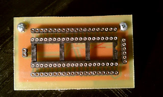
Here's a picture of the bottom solder that's as bad as the soldering job:

I printed out a pin "cheat sheet" for the microcontroller in lieu of a stencil:

Now, to test it out with a hello world style blinking LED!

Soldering was very different from either a proto-board or a professional PCB. The solder and heat want to go everywhere. The ground plane was particularly a problem. I have to admit, I rushed the soldering. I was so excited that everything looked good. I just wanted to see the board done. Here's the top with the pins and sockets added:

Here's a picture of the bottom solder that's as bad as the soldering job:

I printed out a pin "cheat sheet" for the microcontroller in lieu of a stencil:

Now, to test it out with a hello world style blinking LED!
Sunday, April 29, 2012
Etching Your Own PCBs
I decided to have a go at etching my own PCB. It looks like it will be a while before I get around to building my CNC router, so I thought I'd give a thought to making boards the chemical way. I've been a bit put off by the idea of having strong acids in the house, so I never got around to trying this. As luck would have it, I've been following Quinn Dunki's "Blondie Hacks" blog for a bit, watching her develop her own computer from scratch. She posted a blog, detailing her PCB making process. I was surprised to find that she does her etching with Hydrogen Peroxide, White Vinegar, and Salt. That sounded a lot safer than HCL! I checked with my wife ( a chemistry ( and physics, and calculus ) teacher ). She gave me the basics of the chemistry and seemed to think it would work. Here's what happened.
First, I read Quinn's blog about a hundred times. She links to the Sparkfun tutorials about EagleSoft CAD. These are the same tutorials I had used to get started. They are excellent, and Eagle is free ( as in beer ). She also has links to most of the materials you will need. I got alot of stuff from the dollar store ( peroxide, acetone, tupperware, foam brushes, picture frame, cotton balls, funnel, etc ). I was ordering from mouser.com anyway, so I got my presensitized PCB and Positive Developer there. I can't say enough good things about mouser. Once you get used to their search filters, you can find almost anything there.
I have to take a detour here and talk about mouser a bit more. I thought their shipping prices were a bit high. Then, I got my package. I had ordered some new microcontrollers, some SOJ SRAM, some 74HC logic chips, and other stuff with my PCB and developer. Wow! I thought they were delivering medical supplies. The careful packaging, the anti-static bubble wrap, all kind of blew me away. The craziest was the packaging on the SRAM. It came in an anti-static silver baggy, of course. On that was the usual yellow warning label that this was a static sensitive device. In addition was a label that looked like the instructions for handling an human organ tranfer. We're talking about expiration times, humidity controls, temperature controls; you name it. Inside the bag ( once I got the courage to open it ), I found 3 silica gel packs and a Ph sensor card along with a small black box. The box had additional warning and control information. Inside the box, in tons of carefully arranged anti-static foam, were my two little SRAMs. Did I mention that everything was in English? And most of the entries were hand written. I was very impressed.
Anyway, back to board etching. I decided to start with a simple board. I got a new Pic18F4550 and decided to make a carrier board for it. First up was the schematic in Eagle:

From this, I made a board, following Quinn's advice on hole size, ground plane, etc. I won't repeat everything she says. Go read her blog. It's well done. Here's the board:

Nice and simple, and it won't need any jumpers. I did forget to add in the decoupling cap though. Doh!
From there, I printed the board as a PDF file and edited it with GIMP. I printed this board along with the next one I'll try ( line follower sensor ) on acetate. I found some HP transparencies that work with an inkjet printer. They have a rough texture on the printing side that helps absorb and hold the ink. They dry quickly and come out very dark:
 Still, I doubled them up as Quinn suggests. This seems to have made a difference. Taping them together wasn't as much of a pain as I thought it would be:
 Then, it was on to the darkroom. I used my basement workshop/office. Luckily, I have a ton of red LEDs sitting around down there. I threw ten on my breadboard to use as a darkroom light:
 It was dark, but it did the job. I had a bit of trouble when I put the board onto the glass. It was tough to see if the board was aligned with the artwork. For no particular reason, here are the LEDs on:

Behind the LEDs, you can see the bench power supply I made from an old PC PSU. I forgot to blog that one up as I did it. Oh, well. It's great. Right now, It supplies 12, 5, and 3.3V with plenty of amps. Here's the board under exposure:

Here's the developer bath all ready to go. I didn't have time or light to take pictures here.
 Behind the tupperware, you can see my three new stepper motors. I hope to use them to build my CNC. They're going to be too slow, but they should work. Also, to the left, you can see the proto board for the line sensor and my robot behind it. To the right, you can see a bunch of new chips I got from Mouser.
After developing and a quick rinse, it was on to the garage for etching. I mixed equal parts of hydrogen peroxide and vinegar. The etching was *really* slow. I'm glad I brought along a healthy cup of salt. The salt acts as a catalyst for the reaction. I think my tupperware is too small. Next time, I'll use a bigger one to speed up the reaction. Here's the board just dropped in the etchant:
 And here is the final product:
 I left the resist on for now. I'm waiting for my drill bits to arrive. With luck, I won't peel off too many pads!
First, I read Quinn's blog about a hundred times. She links to the Sparkfun tutorials about EagleSoft CAD. These are the same tutorials I had used to get started. They are excellent, and Eagle is free ( as in beer ). She also has links to most of the materials you will need. I got alot of stuff from the dollar store ( peroxide, acetone, tupperware, foam brushes, picture frame, cotton balls, funnel, etc ). I was ordering from mouser.com anyway, so I got my presensitized PCB and Positive Developer there. I can't say enough good things about mouser. Once you get used to their search filters, you can find almost anything there.
I have to take a detour here and talk about mouser a bit more. I thought their shipping prices were a bit high. Then, I got my package. I had ordered some new microcontrollers, some SOJ SRAM, some 74HC logic chips, and other stuff with my PCB and developer. Wow! I thought they were delivering medical supplies. The careful packaging, the anti-static bubble wrap, all kind of blew me away. The craziest was the packaging on the SRAM. It came in an anti-static silver baggy, of course. On that was the usual yellow warning label that this was a static sensitive device. In addition was a label that looked like the instructions for handling an human organ tranfer. We're talking about expiration times, humidity controls, temperature controls; you name it. Inside the bag ( once I got the courage to open it ), I found 3 silica gel packs and a Ph sensor card along with a small black box. The box had additional warning and control information. Inside the box, in tons of carefully arranged anti-static foam, were my two little SRAMs. Did I mention that everything was in English? And most of the entries were hand written. I was very impressed.
Anyway, back to board etching. I decided to start with a simple board. I got a new Pic18F4550 and decided to make a carrier board for it. First up was the schematic in Eagle:

From this, I made a board, following Quinn's advice on hole size, ground plane, etc. I won't repeat everything she says. Go read her blog. It's well done. Here's the board:

Nice and simple, and it won't need any jumpers. I did forget to add in the decoupling cap though. Doh!
From there, I printed the board as a PDF file and edited it with GIMP. I printed this board along with the next one I'll try ( line follower sensor ) on acetate. I found some HP transparencies that work with an inkjet printer. They have a rough texture on the printing side that helps absorb and hold the ink. They dry quickly and come out very dark:


Behind the LEDs, you can see the bench power supply I made from an old PC PSU. I forgot to blog that one up as I did it. Oh, well. It's great. Right now, It supplies 12, 5, and 3.3V with plenty of amps. Here's the board under exposure:

Here's the developer bath all ready to go. I didn't have time or light to take pictures here.

After developing and a quick rinse, it was on to the garage for etching. I mixed equal parts of hydrogen peroxide and vinegar. The etching was *really* slow. I'm glad I brought along a healthy cup of salt. The salt acts as a catalyst for the reaction. I think my tupperware is too small. Next time, I'll use a bigger one to speed up the reaction. Here's the board just dropped in the etchant:


Monday, March 26, 2012
64-bit Woes, Pickit 2, and pk2cmd
Okay, so the old laptop finally died. I'd been calling it the "ghetto laptop" for a few months. Power issues, overheating, cracked the hinge on the lid, etc. The cracked lid gave rise to the nickname ghetto laptop. I had to open and close it by placing a flathead screwdriver in the security lock hole. All it needed was some duct tape on the cover! Then the DVD drive died. Oh well. Then the screen went out.
In panic, I ordered the third most expensive laptop I could find without doing any real research. It's a great machine... unless you like Linux. I do. The problem is that it has an Optimus setup. This means that it has an integrated Intel graphics card hooked directly to the monitor. It also has a dedicated Nvidia graphics card with dedicated 1.5 GB of Ram. This card is hooked *through* the Intel card. The software is meant to handle the switching on/off of the 2 cards. No one felt the need to provide these specs to the open source community, so Linux support is primitive at best at present.
I managed to get everything setup, and I'm now running bumblebee. Great work and thanks to the folks who are working on the bumblebee team! This allows me to run normal stuff from the Intel card and start apps that need better graphics with the Nvidia card.
I also decided that 64-bit OSes were common enough now that I would install one, too. Turns out that this caused a few headaches. One of the worst was with my Pickit 2 programmer. The open source programming software, pk2cmd, would only work with my 16F88 chips! I posted to the pickit-devel group on Google Groups. I managed to attract the attention of two of the main developers of the software, Jeff Post and Xiaofan Chen. After much testing, I ended up compiling pk2cmd as a 32 bit app. It looks like some work would have to be done to make it work for my hardware and kernel under 64 bit. As the programmer and software is pretty old, I doubt that much will (or should) be done.
As notes to myself ( and anyone who may need this ), here's how I got it to compile as a 32 bit app under a 64 bit system. As I don't really do C programming, this was more of a challenge than I expected. The end solution is quite simple.
I pulled in the libusb-devel packages, g++, etc. as recommended in the readme. I also needed to pull in the libusb-0.1.so.4.4.4 library for 32 bit. I altered the Makefile for 32 bit compilation by adding the switch '-m32' ( without the quotes ) to the definition of OPTS:
OPTS=-Wall -m32 -D_GNU_SOURCE $(DBG)
With this, make linux was able to compile the program, but it could not find the library libusb. So, I su-ed to root and found the 32-bit libusb-0.1.so.4.4.4 library in /lib. I changed directories to /usr/lib and made a symbolic link to it as follows:
ln -s /lib/libusb-0.1.so.4.4.4 libusb.so
I then changed the LDFLAGS definition in the Makefile to look like this:
LDFLAGS=-L/usr/lib -lusb
With this, make linux was able to link the files and create the executable. Su and make install had everything working the way it used to. Huzzah!
In panic, I ordered the third most expensive laptop I could find without doing any real research. It's a great machine... unless you like Linux. I do. The problem is that it has an Optimus setup. This means that it has an integrated Intel graphics card hooked directly to the monitor. It also has a dedicated Nvidia graphics card with dedicated 1.5 GB of Ram. This card is hooked *through* the Intel card. The software is meant to handle the switching on/off of the 2 cards. No one felt the need to provide these specs to the open source community, so Linux support is primitive at best at present.
I managed to get everything setup, and I'm now running bumblebee. Great work and thanks to the folks who are working on the bumblebee team! This allows me to run normal stuff from the Intel card and start apps that need better graphics with the Nvidia card.
I also decided that 64-bit OSes were common enough now that I would install one, too. Turns out that this caused a few headaches. One of the worst was with my Pickit 2 programmer. The open source programming software, pk2cmd, would only work with my 16F88 chips! I posted to the pickit-devel group on Google Groups. I managed to attract the attention of two of the main developers of the software, Jeff Post and Xiaofan Chen. After much testing, I ended up compiling pk2cmd as a 32 bit app. It looks like some work would have to be done to make it work for my hardware and kernel under 64 bit. As the programmer and software is pretty old, I doubt that much will (or should) be done.
As notes to myself ( and anyone who may need this ), here's how I got it to compile as a 32 bit app under a 64 bit system. As I don't really do C programming, this was more of a challenge than I expected. The end solution is quite simple.
I pulled in the libusb-devel packages, g++, etc. as recommended in the readme. I also needed to pull in the libusb-0.1.so.4.4.4 library for 32 bit. I altered the Makefile for 32 bit compilation by adding the switch '-m32' ( without the quotes ) to the definition of OPTS:
OPTS=-Wall -m32 -D_GNU_SOURCE $(DBG)
With this, make linux was able to compile the program, but it could not find the library libusb. So, I su-ed to root and found the 32-bit libusb-0.1.so.4.4.4 library in /lib. I changed directories to /usr/lib and made a symbolic link to it as follows:
ln -s /lib/libusb-0.1.so.4.4.4 libusb.so
I then changed the LDFLAGS definition in the Makefile to look like this:
LDFLAGS=-L/usr/lib -lusb
With this, make linux was able to link the files and create the executable. Su and make install had everything working the way it used to. Huzzah!
Monday, January 16, 2012
IR Distance Sensing
Finally got back into distance sensing today. Had the day off for MLK, jr. Did a lot more research and RTFMing. Hooked up a test rig with the following notes:
Distance Detection with IR Led and IR Phototransistor
================================
2012.01.16 -
-----------------
So, it's back to distance detection with IR Leds and IR phototransistors.
I used the IR pair from Radio Shack. A few comments on these, so I don't
forget yet again, I'm sick of re-learning this. The dark one is the emitter.
The clear one is the detector. The emitter has the following key properties:
Forward Current: 150 mA
Forward Voltage: 1.3 V typical. max is 1.7 V
Reverse Voltage: 5 V
Wavelength: 950 nm
Resistance is calculated as always for a diode:
Vs = voltage source
Vf = forward voltage
I = forward current
So,
Vs - Vf
_______ = resistance for max current.
I
For the Radio Shack emitter at 5V source:
5 - 1.3 / .150 = 24.66666
I use a 33 Ohm resistor to get ~112mA.
The big reminder:
1. The long lead does not always mean hook to Positive!!!!
On the emitter, the long lead corresponds to the flat part of the casing.
This corresponds to the Anode ( positive ) lead of the Led.
On the phototransistor, the long lead hooks to the flat part of the part.
The flat part, short lead is the Collector and goes to positive!!!
The round part, long lead goes to the emitter ( ground ).
o Control the IR Led from the microcontroller by triggering an NPN transistor.
I got good results with a 2N3904. I used a 1k resistor to the base.
o The emitter uses a 33 Ohm resistor as calculated above. If you can find
something closer to 25 Ohms, use that.
o The detector gets unresisted 5V to the collector. The emitter goes to ground
via a 100k resistor. The detection line to the microcontroller is hooked
to the emitter.
Results:
----------
Using a hand or white piece of paper, good results went almost 30cm.
Non-precise measurements:
value | value
cm | hand | white paper
--------------------------------
1 | 553 | 1023
2 | 391 | 820
3 | 279 | 620
4 | 199 | 438
5 | 162 | 351
6 | 126 | 272
7 | 113 | 231
8 | 98 | 194
9 | 89 | 166
10 | 79 | 144
11 | 75 | 132
12 | 70 | 118
13 | 67 | 109
14 | 63 | 99
15 | 61 | 88
16 | 57 | 83
18 | 52 | 74
20 | 50 | 66
22 | 48 | 61
24 | 46 | 56
26 | 45 | 54
28 | 44 | 51
30 | 44 | 49
I hooked up a test rig to get these results. Here is the code:
sense source code
As usual, this is assembly source code for a PIC microcontroller from Microchip. In this case, I'm using my little work horse, the 16F88, running at 8 MHz.
Here are some photos of the rig on breadboard:


I'll whip up a schematic soon.
EDIT:
And here it is in somewhat rough shape:

Distance Detection with IR Led and IR Phototransistor
================================
2012.01.16 -
-----------------
So, it's back to distance detection with IR Leds and IR phototransistors.
I used the IR pair from Radio Shack. A few comments on these, so I don't
forget yet again, I'm sick of re-learning this. The dark one is the emitter.
The clear one is the detector. The emitter has the following key properties:
Forward Current: 150 mA
Forward Voltage: 1.3 V typical. max is 1.7 V
Reverse Voltage: 5 V
Wavelength: 950 nm
Resistance is calculated as always for a diode:
Vs = voltage source
Vf = forward voltage
I = forward current
So,
Vs - Vf
_______ = resistance for max current.
I
For the Radio Shack emitter at 5V source:
5 - 1.3 / .150 = 24.66666
I use a 33 Ohm resistor to get ~112mA.
The big reminder:
1. The long lead does not always mean hook to Positive!!!!
On the emitter, the long lead corresponds to the flat part of the casing.
This corresponds to the Anode ( positive ) lead of the Led.
On the phototransistor, the long lead hooks to the flat part of the part.
The flat part, short lead is the Collector and goes to positive!!!
The round part, long lead goes to the emitter ( ground ).
o Control the IR Led from the microcontroller by triggering an NPN transistor.
I got good results with a 2N3904. I used a 1k resistor to the base.
o The emitter uses a 33 Ohm resistor as calculated above. If you can find
something closer to 25 Ohms, use that.
o The detector gets unresisted 5V to the collector. The emitter goes to ground
via a 100k resistor. The detection line to the microcontroller is hooked
to the emitter.
Results:
----------
Using a hand or white piece of paper, good results went almost 30cm.
Non-precise measurements:
value | value
cm | hand | white paper
--------------------------------
1 | 553 | 1023
2 | 391 | 820
3 | 279 | 620
4 | 199 | 438
5 | 162 | 351
6 | 126 | 272
7 | 113 | 231
8 | 98 | 194
9 | 89 | 166
10 | 79 | 144
11 | 75 | 132
12 | 70 | 118
13 | 67 | 109
14 | 63 | 99
15 | 61 | 88
16 | 57 | 83
18 | 52 | 74
20 | 50 | 66
22 | 48 | 61
24 | 46 | 56
26 | 45 | 54
28 | 44 | 51
30 | 44 | 49
I hooked up a test rig to get these results. Here is the code:
sense source code
As usual, this is assembly source code for a PIC microcontroller from Microchip. In this case, I'm using my little work horse, the 16F88, running at 8 MHz.
Here are some photos of the rig on breadboard:

The Full Rig With Ruler

Closer View of the Board

Very Close View of Connections
I'll whip up a schematic soon.
EDIT:
And here it is in somewhat rough shape:

Subscribe to:
Posts (Atom)