Search This Blog

Saturday, November 19, 2011

Light Sensing With an LED

   I want to make a small robot that will run on two vibro motors.  Unlike simple bristlebots, this wants to be a true robot.  It will use a small, 18 pin Pic16F88 microcontroller, controlling the motors with PWM at 5kHz.  For sensors, it wants something simple.  It will be a photovore, turning toward the brightest light source.

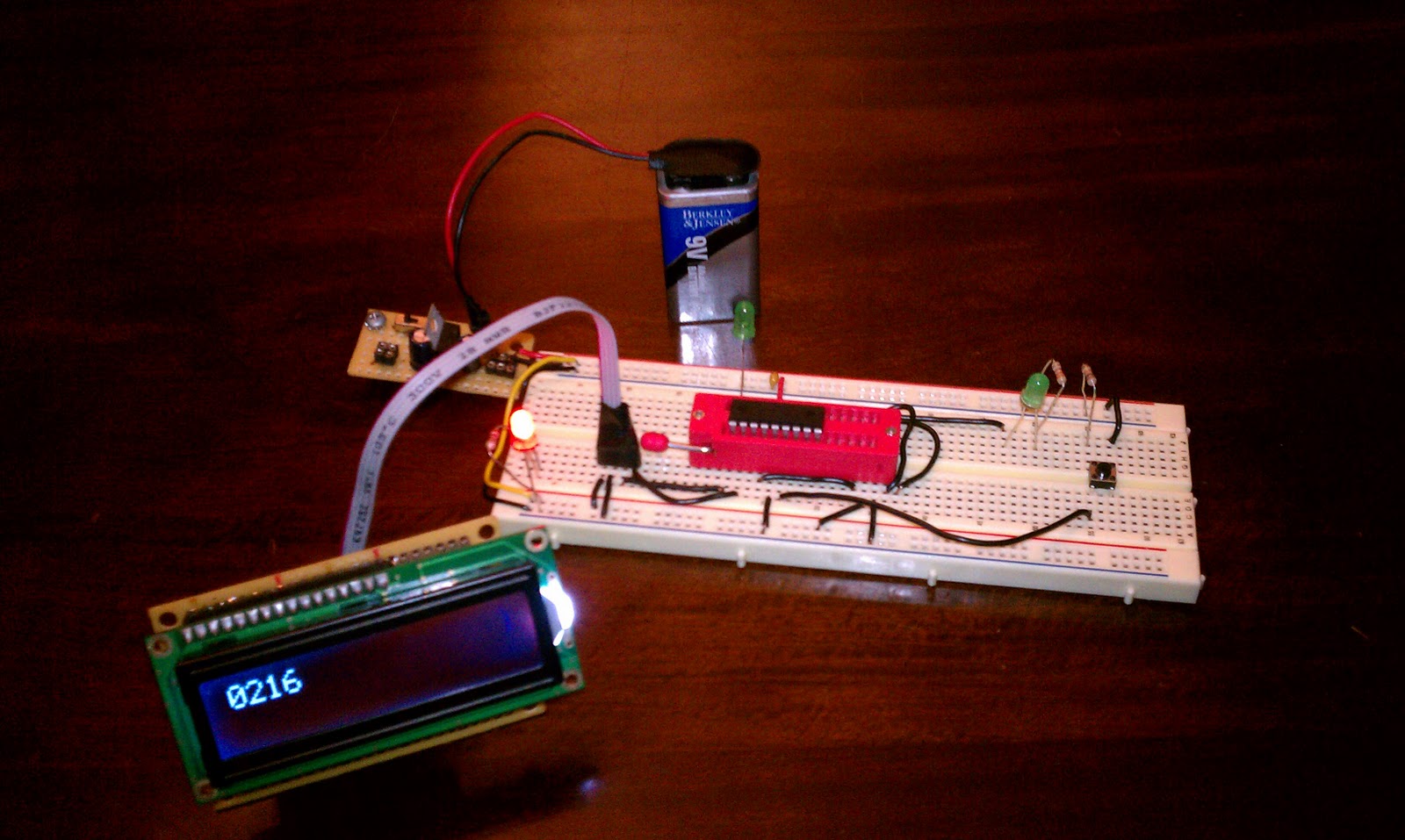
   The robot will use the simple fact that an LED can sense light levels as well as emit light.  To test this fact, I built a simple rig that can measure the light level as an analog voltage level over ADC.  The following set up hooks up an LED to pin RA1 on the Pic16F88.  The anode (positive, longer lead) is hooked to RA1.  The cathode is set to ground.  I hooked up a normally low button to ground with a 10k resistor.  When pressed, it sends 5V to RB0.  RB0 on the Pic16F88 is set up to interrupt on the rising edge.  I flash an LED on RB4 for half a second when the interrupt occurs.  I then execute an ADC conversion on RA1 (AN1).
 
   I took some code from the PicList to convert a 12 bit (2 byte) value from the ADC (ADRESH and ADRESL) and convert it to 2 packed bytes in BCD values.  By adding 48 to each nibble, I can display the thousands, hundreds, tens, and ones places as ASCII values on an LCD screen.  The ADFM value of ADCON1 is set to right justify the 10 bit value.  This means that the 6 most significant bits of the ADRESH byte are read as zero.  This simplifies the conversion to BCD.

   Here are my notes for the values for ADC with the Pic16F88 at 8MHz:

For Pic16F88, operating at 8 MHz.

Minimum Time of Acquisition: 19.72 us ( from the datasheet )
Minimum TAD: 1.6us ( max is 6.4 us )

Fosc = 8 MHz
Tosc = 125ns (1.25 x 10^-7)

Minimum Conversion setting = 16 x Tosc
16 * 125ns = 2us ( which is greater than the minimum TAD )

Total time to complete a reading is Acquisition time + 11 * Tad:
19.72 + ( 11 * 1.6 ) = 37.32 us  .00003732 or 3.732 x 10^-5

Max Sampling Frequency: 1 / 37.32 us = 26795 samples/second


   One gotcha with this set up.  The PORTB pins of the Pic default to having a pull up resistor on each pin,  This prevented the Pic from detecting the transistion from low ( with a 10k resistor ) to high.  I disable the pull ups by disabling the pull ups on bit 7 of the OPTION register.  Kinda backwards, you disable the pull ups by setting bit 7 of the OPTION register.

   I tested red, green and IR leds.  The red LED seems to provide the best range of values and sensitivity.  Here are the red and green values.  The IR was flaky enough that I didn't record the values.

green
dark: 130
low: 219
high: 255

red
dark: 115
low:    175
high: 233

Dark was my fingers and sleeve covering the LED.  Low was the low light level present in my living room.  High was the "flashlight" app of my smartphone on highest intensity pointed directly at the LED from a distance of about 3 inches.

Here are some pictures of the breadboard layout:


Here is the schematic:

And here is a link to the source code:
Sense Light Level On Button

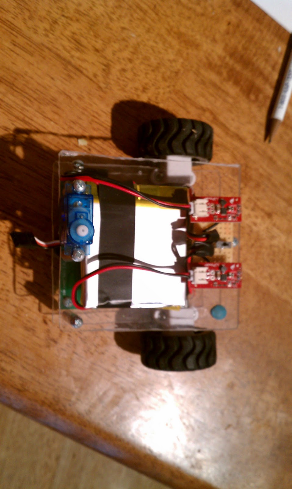
   Two analog pins could sense two LEDs for left right light levels.  They will adjust the level of vibration accordingly.  Each motor will get 3 pins for PWM, totaling 75 mA of current.  The whole thing will be run by a small, rechargeable lion coin cell battery ( 3.7 V, 110 mAh ).  The Pic and motors will run well at this level.  I'm not sure what the ADC will look like.  I'll have to experiment further.

Here is the coin cell and its holder ( that will allow for recharge ):


   I'll build a small carrier board for the whole thing.  I still need to figure out how to hold the battery.  I don't want to use the holder as this would involve too much weight and bulk.  I need to create the legs, too.  I'll use a toothbrush or two or maybe some paper clips.  Who knows?

Sunday, November 13, 2011

Newest Pictures of Newest Bot

Quick dump of pictures of my latest version of my new bot:


Thursday, November 3, 2011

Micro SD Card - Low Level I/O

   This has been a most satisfying week.  With the help of Marcus Bannerman and his well laid out website, I now have low level routines working to read, write, and erase an SD card.  Marcus, if you are reading this, thank you again for all your help.  This working code is really all his for the SD card routines.  Here is a link to his site at the Fat32 library page, complete with tutorials, a forum, and loads of helpful information, all backed by a very generous and intelligent man: marcusbannerman.co.uk.  I used a version 2, low capacity, 2 GB Sandisk micro SD card for my stuff, but I am confident that Marcus' code will work for almost any card.  I haven't tried the FAT library yet, but it looks really useful.  I'm satisfied with low level reading and writing on an unformatted card.  I'll let my application transfer data to a PC as needed.  If I'm really in a bind, I'll do what I did when debugging.  I simply insert the card and use:
$sudo dd bs=512 count=2 if=/dev/sdx of=dump
to spew out the data.  You'll have to adjust the parameters for your use, of course.  I've heard that if you are going to do a full dump of the card, it is best to set a really high value for the bs.

[ On a side note, it was interesting to dump out the raw data from the card and look at it.  I had never used the card before, yet there was a host of plain text and other stuff on the card.  Most of it was in French. Try it sometime.  I zeroed out the entire card before I began working on it with dd and the if= set to /dev/zero. ]

   Here are the links to my code for the Pic18F2455, running at 20MHz:
logger.asm (main routine)
20MhzConfig.conf
sdMacros.asm
lcd-serial.asm
sdCard.asm

   The conf file sets all the fuses.  The way gpasm has you lay out the fuses for the 18F Pics is rather long.  It was cluttering up the files, so I made it its own include.  The logger file is the main routines.  It also includes delay routines that are usable at 4, 8, 16, and 20 MHz.  A define statement sets the loop based on the clock.  The LCD routines are for your basic 2 line Hitachi based LCD.  I have the code set up for 6 wire interface, four data in four bit mode, RS, and E.  RW is tied to ground.  I wired mine up to a little backpack with an 8 bit logic shifter.  This way, it only takes two I/O lines from the Pic, Vdd, and ground to run.  Myke Predko has a cool method of tying the data line to the E pin on the shifter that acts as an AND gate.  This lets you strobe with the data line with the clock not strobing.  Here is a link to Myke's work: 2 Wire LCD Interface.  The lcd function duplicates some delay routines.  I jammed it together with the sd code pretty quickly.  I'll need to clean it up later.

   Below are some shots of my test rig.  I'm running the Pic and LCD at 5V.  I have a voltage regulator to power the SD card and shift the voltage for the SD card.  Marcus' site has a good Eagle schematic.


Above is the whole assembly.  The Pic lives in my carrier board that BatchPCB made from my Eagle design.  It includes the resonator, smoothing cap, and an ICSP header.  On the right is the LCD and backpack.  Behind the ribbon cables is the micro SD card in a breakout board.  The upper far left corner is my voltage regulator for five Volts.  Here are some closeups:

Overhead shot of the SD card breakout and level shifter circuit.

The Pic carrier board

LCD Logic Shifter Backpack

5 Volt regulator

   The ribbon cables are like the one I posted about previously.  They're made from old IDE cables and swiss machine pin headers.  I need to make more of these.  They're really great for neatening up a layout.