Search This Blog

Tuesday, December 20, 2011

IR Remote Control

So, I bought this:


   It's an IR Receiver module that operates on IR signals modulated at 38 kHz.  It has three terminals for Vcc, Ground, and signal Out.  The Out signal is normally high ( digital one ).  When it detects a pulse modulated width signal with a period of 38 kHz ( with a duty cycle somewhere around 1/3 to 1/2 ), the out signal goes low ( digital 0 ).  This component has a great range and arc, and it ignores just about anything else around it.  It's typical of the IR receiver on your TV, stereo, etc. 

   I had an old JVC stereo remote, and I wanted to see if I could decode its signals with this component on my Pic 16F88.  I did a bit of Google research on IR protocols.  The first thing to note in hindsight: If you can, use a Sony remote!!  Their protocol is by far the easiest one I found.  It has clear, easy to detect boundaries that all focus on what will be the low signals you receive.  That said, I had a JVC remote lying around that wasn't connected to anything I needed.  The information on this protocol was not as clear as it could have been.  I'll attempt to clear some of that up here if I can. 

   JVC uses space-width codification for its transmission.  This means that the length of time a signal is high or low is of great importance.  Everything is based on a basic time unit, T.  For JVC, this time interval is defined as 527 us +/- 60 us.  For my tests,
we split the difference and assume that T is 560 us.  From the anals of days past, the protocol wants to send a start sequence.  This sequence was intended to help receivers calibrate themselves to the sender.  It is basically unpredictable when this sequence will be sent.  Every remote seems different.  We will eventually ignore it.  The bulk of a send consists in 16 bits ( 2 bytes or 1 word ) of information sent.  The first 8 bits is the address.  This is an identifier for the device.  The next 8 bits is the command.  Both of these bytes are sent Least Significant Bit first.  Here's the tricky part:  The documentation I found on the Web doesn't say much about the end of the packet.  There IS A STOP BIT!!! More on that in a bit.

   From the point of view of the IR component ( and microcontroller ), the signal is usually high.  The tendency is to want to pay attention to the low signals.  With Sony, this is true and easy.  With JVC, the time significant signals are high is what is
important.  It turns out that there are 2 low "marks" and 4 high "spaces" to watch for:

-----------------------
       Times
-----------------------

Low Marks:
----------
Header Mark:    8.44 ms
Bit Marks:         527 us   ( T )

High Spaces:   
------------
Header Space:    4.22 ms
Zero:                   527 us   ( T )
One:                    1.58 ms ( 3T )
Word Space:      12.53 - 29.54 ms


   Here's what a transmission looks like from the point of view of a microcontroller:


   Every bit begins with the line going low for time T.  The ONLY time the line ever goes low is to signal either a header or the start of a bit.  The trick is to know where we are in a transmission.  Retransmits ( any transmit where we don't have a header ) just start firing bits.  We need to know that we are at the FIRST bit of the tranmission.  The only way to be sure of this is to make sure that no bit transmission stays high too long. 

   Here's how it breaks down.  We look for the signal to go low.  We wait for it to go high.  We wait for 1.5 T.  If the signal has gone low, we have a zero transmitted.  We are halfway into the bit mark for the next bit.  If the signal is still high, we wait 2T ( total time elapsed 3.5T ). If the signal has gone low, we have a one and we are halfway into the bit mark for the next bit.  If it is still high, we are in either the header or the wait time after a stop bit.  Either way, we are mis-aligned, so we return and wait for a better start position. 

   The stop bit is a normal pull low for time T.  Then, a time of 12.53 - 29.54 ms will be high. 

   Here's what works:

Signal goes low, call getIrData.

getIrData
    ; setup, init values
    movlw    0x80                            ; load dataPacket with 128.
    movwf    dataPacket
    clrf    addressPacket
getBitLoop
    ; Wait for line to go high
    btfss    irPortBit
        goto    getBitLoop

testIrHighTime
    ; wait for 1.5 T
    call    delay700us
    btfss    irPortBit
        goto    bitIsAZero    ; shift in a zero
    ; now wait 2T. This will either put us .5T into the start mark of the next bit, or an error
    call    delay1ms
    btfss    irPortBit
        goto    bitIsAOne
    ; Here, we are in a misalignment zone.  We are either in the high time of a start bit
    ; or in the rest time between repeats.  Clean up and return.
    return

bitIsAZero
    ; Signal is now low.
    ; bit is a zero. rotate zero in.
    bcf        STATUS,C
    rrf        dataPacket,F
    rrf        addressPacket,F
    ; if Carry is set, we've acquired 16 bits and we are done.
    btfss    STATUS,C
        goto    getBitLoop
    ; if it is set, go wait for the stop bit.
    goto    waitForStopBit

bitIsAOne
    ; Signal is now low.
    ; Bit is a one. rotate one in.
    bsf        STATUS,C
    rrf        dataPacket,F
    rrf        addressPacket,F
    ; if Carry is set, we've acquired 16 bits and we are done.
    btfsc    STATUS,C
        goto    getBitLoop
waitForStopBit
    ; signal is low.  Wait for high
    btfss    irPortBit
        goto    waitForStopBit
    ; Now we can send our packets


  Here is the full code: Read IR Test Code

  In the init of getIrData, we put a one in the eighth bit of the addressPacket.  The data is coming to us address, then data, and each will come least significant bit first.  So, we will rotate each data bit we receive through the data packet, then the address packet.  When we use the rrf rotate function, it takes what is in the Carry bit of the STATUS register and pushes that on the eighth bit of the dataPacket.  If the bit received is a one, the code puts a one in Carry and shifts it onto the eighth bit of dataPacket.  This shifts every bit to the right.  The one that is placed on the eighth
bit of dataPacket will eventually pop out and go into the Carry ( rotate is like a loop of the register and the Carry flag ).  The code can check the Carry bit for a one to see if all 16 bits have been received. 

   The testIrHighTime routine serves two very important functions.  First, it waits 1.5T ( ~700 us ).  This places the code about .5T past where a zero signal would end.  If the signal has gone low already, the code knows we received a zero.  If it is still high, the code waits an additional 2T.  This places it .5T past where a one would end.  If it has gone low, the code processes a one.  If it is still high, then one of two things has happened.  Either a start header is being sent, or the signal is in the high time of a stop bit when the code was not expecting it.  In either case, we simply return.  The
next low signal will pop in again.  Eventually, it will align at the start of a signal and read the packets.

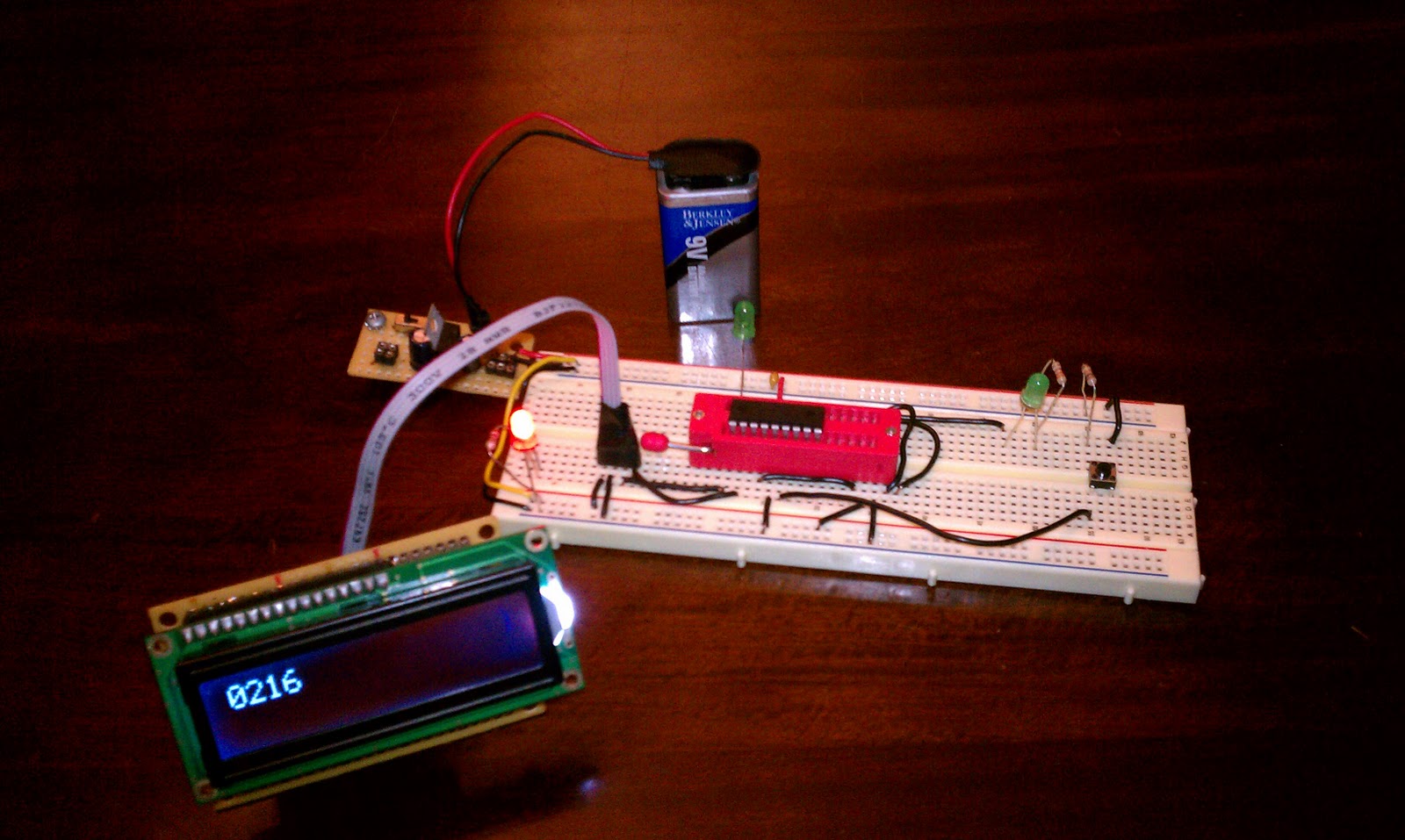
Here is a picture of a simple test rig.  Note, the numbers being displayed are wrong.  I was still fiddling with the routine when I took the pictures. 


Here are the codes for my stereo remote:

Address: 10011111  ( Decimal 159, Hex 0x9F )


Value        Code        Decimal        Hex
 1        00100001      33              0x21
 2        00100010      34              0x22
 3        00100011      35              0x23   
 4        00100100      36              0x24
 5        00100101      37              0x25
 6        00100110      38              0x26
 7        00100111      39              0x27
 8        00101000      40              0x28
 9        00101001      41              0x29
10       00101010      42              0x2A
10+    00101110      46              0x2E

Disk:
1        11110001     241        0xF1
2        11110010     242        0xF2
3        11110011     243        0xF3
4        11110100     244        0xF4
5        11110101     245        0xF5
6        11110110     246        0xF6

Power        00000000       0        0x00
Volume Up    00000001       1        0x01
Volume Down    00000010       2        0x02

EDIT
    On Feb 3rd, 2012, I received an inexpensive logic analyzer that I had ordered.  It is the Open Workbench Logic Sniffer.  I was able to capture the signals coming in from the IR remote.  Here is a shot of the header, address, command for the "10" key:


I'm pretty stoked to have this little guy even if the memory is small.

Saturday, December 17, 2011

Programming 16F Series Pics WIth pk2cmd

   Okay, this has happened before.  I solved it and forgot how I did it.  Lesson learned.  Here is the problem and solution.  I'm using a PicKit2 programmer with the open source pk2cmd software on Linux to program my Microchip PICs.  Most of the time, I have no problem.  Today, my 16F88 simple failed to do an erase and verify blank.  After a ton of Googling, I found a post that suggested that the -X switch may help.  This switch raises VPP before VDD.  I tried it, and it works!  Here are some samples:

pk2cmd -ppic16f88 -x -e
pk2cmd -ppic16f88 -x -c
pk2cmd -ppic16f88 -x -mcp -fmyCoolProg.hex

More later!

EDIT: So, I had the same troubles with my PIC18F2455 the other day.  This freaked me out a bit because I don't have the picp software for my PicStart Plus programmer anymore, and I don't think it can program my 18F2455s.  I tried the trick above, but it didn't work.  After a few deep breaths, I fiddled around a bit more.  The PicKit2 could identify the chip correctly when I used autodetect ( -p ).  I tried an erase and verify with autodetect, and it worked!  So, if you have trouble, first try autodetect.  If that doesn't work, try the voltage trick above.  If it does work, try using autodetect:
 pk2cmd -p -e
 pk2cmd -p -c
 pk2cmd -p -mcp -fmyCoolProg.hex

Once this has worked, the PicKit2 was able to take a chip reference again with no problem.  I was programming 2 different chips ( 16F88 and 18F2455 ) back and forth rather rapidly.  I think the PicKit2 just got confused or failed to reinitialize after each programming effort.

Saturday, December 3, 2011

Pulse Width Modulation (PWM) Calculations for PIC Micros

   Pic micros are really awesome little chips, and Microchip does a really good job documenting them.  Usually.  Sometimes, though, their docs assume something that I just completely fail to know about.  One such area was using their built in PWM on the CCP modules.  I could get them working.  I just cheated and used this Pic PWM Calculator.  But, reading their data sheets, I could never understand how the values were computed.  Tonight, I finally took some time to get it.  Here are the fruits of my labors.

   First, a review.  PWM wants to set up a period and a duty cycle.  The period is the length of time of one pulse cycle.  The duty cycle is the percentage of time in the period that the pulse will be high.  For Pic micros, the period is set with register PR2.  The duty cycle is a bit more complex.  It is shared between a register, such as CCPRnL and two bits in a control register such as CCPCONn<5:4>.  The lease significant bits are stored in the CCPCON<5:4> bits.  I'll talk about the simple Pic16F88.  It only has one CCP module, so the CCP register is CCPR1L and the control register is CCPCON. 

   First, the period must be set in register PR2.  For this example, we will set a 38 kHz period for a Pic16F88, running at 8 MHz.  The data sheet says that:

        PWM Period = [(PR2) + 1] • 4 • TOSC • (TMR2 Prescale Value)

A bit of algebra turns that into:

       PR2 = ( PWM Period / ( TOsc x 4 x TMR2 Prescaler ) ) - 1

Definitions:
       PWM Period = 1 / PWM frequency
       TOsc = 1 / MCU clock frequency

So, this looks like this for our 8 MHz Pic for a 38 kHz PWM:

       PR2 = ( ( 1/pulse frequency in Hz ) / ( 1/clock speed x 4 x prescaler value ) ) - 1
       PR2 = ( ( 1/38,000 ) / ( 1/8,000,000 ) x 4 x 1 ) ) - 1
       PR2 = ( ( .0000263 ) / ( .000000125 ) x 4 x 1 ) - 1
       PR2 =  52.6 - 1
       PR2 =  51.6 ( use 52 )

So, PR2 will get the value decimal 52 ( 0x34 ).  The prescaler worked with a simple x1 modifier, so TM2Con will be 0x04 ( 0b00000100 ).  If the value had been greater than 255, the TMR2 prescaler allows values of 1, 4, and 16.  Plug each value into the equation to get a PR2 value between 1 and 255.  If the value is still out of range, the PWM module cannot provide that frequency.  This is especially true of low frequencies needed for servo control.  It is fairly easy to implement those in software.  I've written code that controls 16 servos in software with interrupts.  I'll post that at some point.

    Now, for the duty cycle.  This is the part that drove me nuts.  The data sheet states that the duty cycle is:

    PWM Duty Cycle = (CCPR1L:CCP1CON<5:4>) • TOSC • (TMR2 Prescale Value)

   I couldn't for the life of me get this to translate into sensible values.  I used the PWM calculator to reverse engineer the equation.  Here are the definitions I came up with.

    Duty Cycle = ( 1/ pwm freq ) x percentage
    TOsc = 1 / clock freq.

    So, if I have a FOsc of 8 MHz and want 38 kHz at 50% duty cycle:

    Duty Cycle = ( 1 / 38,000 ) x .50 = .0000132
    TOsc = .000000125
    (CCPR1L:CCP1CON<5:4>) = .0000132 / .000000125 = 105.6
    use 106, in binary = 0b1101010
    So CCPR1L gets 0b11010 and CCP1CON<5:4> gets the lsbs: 0b10

   No matter what, the least significant bits go into CCP1CON<5:4>.  The rest goes into CCPR1L.  Note that the value for duty cycle is only 7 bits long, so my resolution is 7 bits for 38 kHz at 8 MHz.  That's it!

EDIT:
   I've been looking this over again.  The Duty Cycle is the percentage of the period frequency.  So, 50% of 38KHz is:
1/38000*.5 = 1.3157e-5 or ~ 0.00001316
0.0000132 * 8e6 = 105.6

This seems easier to think about.  It's just 1/pwm freq. * percentageAsDecimal * FOsc / prescaler.


Saturday, November 19, 2011

Light Sensing With an LED

   I want to make a small robot that will run on two vibro motors.  Unlike simple bristlebots, this wants to be a true robot.  It will use a small, 18 pin Pic16F88 microcontroller, controlling the motors with PWM at 5kHz.  For sensors, it wants something simple.  It will be a photovore, turning toward the brightest light source.

   The robot will use the simple fact that an LED can sense light levels as well as emit light.  To test this fact, I built a simple rig that can measure the light level as an analog voltage level over ADC.  The following set up hooks up an LED to pin RA1 on the Pic16F88.  The anode (positive, longer lead) is hooked to RA1.  The cathode is set to ground.  I hooked up a normally low button to ground with a 10k resistor.  When pressed, it sends 5V to RB0.  RB0 on the Pic16F88 is set up to interrupt on the rising edge.  I flash an LED on RB4 for half a second when the interrupt occurs.  I then execute an ADC conversion on RA1 (AN1).
 
   I took some code from the PicList to convert a 12 bit (2 byte) value from the ADC (ADRESH and ADRESL) and convert it to 2 packed bytes in BCD values.  By adding 48 to each nibble, I can display the thousands, hundreds, tens, and ones places as ASCII values on an LCD screen.  The ADFM value of ADCON1 is set to right justify the 10 bit value.  This means that the 6 most significant bits of the ADRESH byte are read as zero.  This simplifies the conversion to BCD.

   Here are my notes for the values for ADC with the Pic16F88 at 8MHz:

For Pic16F88, operating at 8 MHz.

Minimum Time of Acquisition: 19.72 us ( from the datasheet )
Minimum TAD: 1.6us ( max is 6.4 us )

Fosc = 8 MHz
Tosc = 125ns (1.25 x 10^-7)

Minimum Conversion setting = 16 x Tosc
16 * 125ns = 2us ( which is greater than the minimum TAD )

Total time to complete a reading is Acquisition time + 11 * Tad:
19.72 + ( 11 * 1.6 ) = 37.32 us  .00003732 or 3.732 x 10^-5

Max Sampling Frequency: 1 / 37.32 us = 26795 samples/second


   One gotcha with this set up.  The PORTB pins of the Pic default to having a pull up resistor on each pin,  This prevented the Pic from detecting the transistion from low ( with a 10k resistor ) to high.  I disable the pull ups by disabling the pull ups on bit 7 of the OPTION register.  Kinda backwards, you disable the pull ups by setting bit 7 of the OPTION register.

   I tested red, green and IR leds.  The red LED seems to provide the best range of values and sensitivity.  Here are the red and green values.  The IR was flaky enough that I didn't record the values.

green
dark: 130
low: 219
high: 255

red
dark: 115
low:    175
high: 233

Dark was my fingers and sleeve covering the LED.  Low was the low light level present in my living room.  High was the "flashlight" app of my smartphone on highest intensity pointed directly at the LED from a distance of about 3 inches.

Here are some pictures of the breadboard layout:


Here is the schematic:

And here is a link to the source code:
Sense Light Level On Button

   Two analog pins could sense two LEDs for left right light levels.  They will adjust the level of vibration accordingly.  Each motor will get 3 pins for PWM, totaling 75 mA of current.  The whole thing will be run by a small, rechargeable lion coin cell battery ( 3.7 V, 110 mAh ).  The Pic and motors will run well at this level.  I'm not sure what the ADC will look like.  I'll have to experiment further.

Here is the coin cell and its holder ( that will allow for recharge ):


   I'll build a small carrier board for the whole thing.  I still need to figure out how to hold the battery.  I don't want to use the holder as this would involve too much weight and bulk.  I need to create the legs, too.  I'll use a toothbrush or two or maybe some paper clips.  Who knows?

Sunday, November 13, 2011

Newest Pictures of Newest Bot

Quick dump of pictures of my latest version of my new bot:


Thursday, November 3, 2011

Micro SD Card - Low Level I/O

   This has been a most satisfying week.  With the help of Marcus Bannerman and his well laid out website, I now have low level routines working to read, write, and erase an SD card.  Marcus, if you are reading this, thank you again for all your help.  This working code is really all his for the SD card routines.  Here is a link to his site at the Fat32 library page, complete with tutorials, a forum, and loads of helpful information, all backed by a very generous and intelligent man: marcusbannerman.co.uk.  I used a version 2, low capacity, 2 GB Sandisk micro SD card for my stuff, but I am confident that Marcus' code will work for almost any card.  I haven't tried the FAT library yet, but it looks really useful.  I'm satisfied with low level reading and writing on an unformatted card.  I'll let my application transfer data to a PC as needed.  If I'm really in a bind, I'll do what I did when debugging.  I simply insert the card and use:
$sudo dd bs=512 count=2 if=/dev/sdx of=dump
to spew out the data.  You'll have to adjust the parameters for your use, of course.  I've heard that if you are going to do a full dump of the card, it is best to set a really high value for the bs.

[ On a side note, it was interesting to dump out the raw data from the card and look at it.  I had never used the card before, yet there was a host of plain text and other stuff on the card.  Most of it was in French. Try it sometime.  I zeroed out the entire card before I began working on it with dd and the if= set to /dev/zero. ]

   Here are the links to my code for the Pic18F2455, running at 20MHz:
logger.asm (main routine)
20MhzConfig.conf
sdMacros.asm
lcd-serial.asm
sdCard.asm

   The conf file sets all the fuses.  The way gpasm has you lay out the fuses for the 18F Pics is rather long.  It was cluttering up the files, so I made it its own include.  The logger file is the main routines.  It also includes delay routines that are usable at 4, 8, 16, and 20 MHz.  A define statement sets the loop based on the clock.  The LCD routines are for your basic 2 line Hitachi based LCD.  I have the code set up for 6 wire interface, four data in four bit mode, RS, and E.  RW is tied to ground.  I wired mine up to a little backpack with an 8 bit logic shifter.  This way, it only takes two I/O lines from the Pic, Vdd, and ground to run.  Myke Predko has a cool method of tying the data line to the E pin on the shifter that acts as an AND gate.  This lets you strobe with the data line with the clock not strobing.  Here is a link to Myke's work: 2 Wire LCD Interface.  The lcd function duplicates some delay routines.  I jammed it together with the sd code pretty quickly.  I'll need to clean it up later.

   Below are some shots of my test rig.  I'm running the Pic and LCD at 5V.  I have a voltage regulator to power the SD card and shift the voltage for the SD card.  Marcus' site has a good Eagle schematic.


Above is the whole assembly.  The Pic lives in my carrier board that BatchPCB made from my Eagle design.  It includes the resonator, smoothing cap, and an ICSP header.  On the right is the LCD and backpack.  Behind the ribbon cables is the micro SD card in a breakout board.  The upper far left corner is my voltage regulator for five Volts.  Here are some closeups:

Overhead shot of the SD card breakout and level shifter circuit.

The Pic carrier board

LCD Logic Shifter Backpack

5 Volt regulator

   The ribbon cables are like the one I posted about previously.  They're made from old IDE cables and swiss machine pin headers.  I need to make more of these.  They're really great for neatening up a layout. 

Saturday, October 22, 2011

Serial LCD With 74HC595

   Worked this weekend on writing to an Hitachi style 2 line, 16 character LCD.  I've posted on this before, but this time I tried a few new things.  First, I'm using the 18F2455.  To slow things down, I'm using a 4 MHz crystal.  I wanted to reduce the number of wires involved in steps.  First, I got the write working in 4 bit mode.  This is where you write a nibble at a time to the RD4-7 pins of the LCD.  Then, I got rid of the busy flag checks I'd used in the past.  I simply wait the maximum time for each operation.  This is 200us for data writes and 5ms for instruction operations.
   Then, the interface wanted less wires.  I added a 74HC595 shifter.  I initially kept the lcd strobe (E) pin on the microcontroller.  This meant I only needed three pins to write to the LCD: E, data, and clock.  Myke Predko passed on a tip he got from an old magazine article.  This lets you set up an AND gate between the 8th pin of the shifter and the data line.  With careful handling, this can serve as the E pin.  I'm attaching a code sample and schematic.  The schematic is illustrative but not exact.  I wouldn't try to create a board from it....
   I plan on making a small backpack for my LCD with the AND gate, the potentiometer, the shifter, and pins for the LCD.

Here's the sample code: lcd-serial.asm
Here's the schematic:

Saturday, May 21, 2011

New Board and Stepper Motors

    My breakout boards for the PIC18F2455 came from BatchPCB.com on Friday.  It looks a little wider than I'd hoped, but other than that, it is great!  Better yet, they sent me two for some reason.  Maybe because it was so small or due to the layout of the panel.  Here it is front and back.  Stencil came out crisply, too.


I soldered in the headers, added a cap, resonsator, and Pic, and voila!

It is really nice to have the labeled pins right on the board, especially the power pins!

    We had e-cycling this weekend, so I had to salvage whatever parts I wanted before all that priceless junk tech went bye bye.  I ripped apart an ancient scanner.  Among the other goodies, I pulled out a stepper motor.  I've never used one, so I thought it would be fun to play with.  I read up on using stepper motors.  A good place to start is: society of robots stepper tutorial.  Here is the motor:


    I was ready for 4 wire bi-polar motors; I was ready for 6 wire uni-polar wires.  This lil' guy has five.  A lot of Googling later, I figured out that it is a variant of a uni-polar stepper.  All four magnets share a common center tap.  After a lot of fiddling, I figured out how it worked.  The center tap will have half of the resistance hooked to any other wire as any other set.  All four end leads will have the same resistance between them.
    To figure out what ends go where, you need to do the following.  Connect the center tap to ground.  I used a nice low, 5 Volt supply.  Hook one lead to Vcc.  Ground the other leads one by one.  If the motor doesn't move at all, that lead is the opposite pole to the lead hooked to positive.  If it twitches clockwise, it is the "cousin" to the positive lead.  If you call the positively hooked lead 1A, the non-moving lead is 1B.  The clockwise twitching lead is 2A.  If it twitches counter-clockwise, that is the 2B.  These letter number pairs will line up to the stepping guides in the Society of Robots tutorial mentioned above.
   Going backwards was also a bit of a trick.  You need to invert either 1A and 1B's values or 2A and 2B's.  Doing both won't get you anywhere.
    I couldn't find *any* information on this motor.  Zero.  Zip.  Nada.  So I guessed and hacked.  I eventually hooked the center tap to ground, ran at 5V, and hooked the leads to a L293D clone.  I slowly increased the frequency from 250 to 1KHz.  I got nothing but twitches at 1KHz.  I settled for 750 Hz.  Even then, I get some rotation starting points that will just twitch.  I think 500 Hz would be more accurate.  I didn't have the stones ( or desire for magic blue smoke ) to try more voltage.

    Here is the breadboard layout:


Here is some code in assembly.  It makes the motor do a full rotation forward, pause 1 sec, rotate half-way backwards, pause, rotate half way forwards, pause, full rotation backwards, loop.

    That's a long way from a home made CNC router, but it was fun.

Sunday, May 1, 2011

A Few Changes to the Robot

   I made some quick little changes to the robot.  I put in the new battery pack with cover and power switch.  The mini servo is now in place but not wired in.  I moved the smoothing cap to the underside of the carrier board.  I put in some quick hookup wires just so I can test the motor driver from the Pic.  Here is a quick, blurry picture:

Saturday, April 30, 2011

Bot Building Day!

   Finally!  A beautiful, sunny weekend with time to work on my new robot.  I cut the acryllic boards for the first layout today, using a Dremel.  I put way more holes in it than planned, and learned alot about how to lay out a chassis.  I built 3 proto boards for the bot's main systems: a carrier board for the brains, a motor driver breakout, and a power regulator board.  When I tested these with the motors, I realized that a single power source of 4 AA batteries was not going to be enough.  I would need a separate power supply for the chips.  I thought it would kill the design I had in mind.  The whole bot was designed to be as small as I could make it.  After some jigsaw puzzle like work, I came up with a new arrangement.  I managed to get all three boards on the bottom layer with the motors.  The top now has the AA battery pack as well as a 9 Volt battery.  It looks a little less pretty, but it will work.  I mounted the 9V at the very back, but this made the bot do wheelies.  I moved it on top of the 6V AA battery.
   The bottom chassis is just 8cm wide by 9 cm long.  The top is 8cm by 10cm.  The extra centimeter allows for the brackets for the servo.  In later bots, the extra centimeter will be on the bottom for the sensor boards.
   I am planning to use all the same basic gear for 3 robots.  The first will have a tiny servo with a Sharp IR sensor on it.  The second will swap these out for a line sensor array on the bottom.  The last will swap this out for 5 IR Led/Phototransistors to sense walls.
  The basic equipment is:

  • 2 Pololu 30:1 Micro Metal Gear Motors - $15.95 USD ea.
  • 2 Pololu Wheel Encoders - $14.95 USD ea.
  • 2 42mm Pololu Wheels ( That work with the encoders ) - $6.95 USD for 2
  • 2 Pololu Extended Motor Brackets - $4.95 USD pair
  • 1 TI SN754410 - a "drop-in" replacement for the L293D - $2.35 USD 
  • 1 5V Voltage Regulator - $1.25 USD
  • 1 Pic 18F2455  - $5.95 USD
  • 1 Pololu Ball Caster - $2.95 USD
  • 1 4 AA batter holder ( The one I'll use has a power switch; not the one shown below ) - $1.99 USD
  • 1 9V battery & 4 1.5 AA batteries
   The mini servo was $8.95 USD and the Sharp IR sensor with pigtail was $14.95 USD.  I haven't put together the other sensor arrays yet.  The proto boards were the little cheap ones from Radio Shack.  They cost a dollar and change.  I used a thin 0.083 sheet of acryllic from Home Depot.  The was about 2 feet by 3 and cost about $7.95 USD.  All of the female pins on the boards are Swiss machine pins ( round holes instead of square ) except for the ICSP header.  The ceramic resonator uses pins, so I can swap out different value.  With this Pic, I can put in a 4MHz crystal and crank it up to 48MHz with PLL.  The total cost of the robot is in the $130-$140 dollar range, adding in the pins, wire, caps, resonator, standoffs, screws, solder, etc.  It weighs in at 137 grams.


   Here are some pictures of the basic assembly.  It's pretty rough, but I'll get better.


   One of the downsides of my hasty layout change is that it is really hard to reach the power switch.  It was supposed to go on the top of the robot.  I bought a new battery holder for the motor's batteries.  It has a built in power switch.  That way, I can catch the bot and kill the motion.  Then I can power down the TTL chips at my leisure.  


   Note the "awesome" soldering job!  I designed boards in Eagle.  I sent the carrier board for the Pic off to batchpcb.com.  If it comes back as a working board, I'll swap out the proto board.  I'll send off the other designs and replace them as well.  More than likely, I'll just get a really little coaster.  We'll see.


   All the junk wire in there are from a quick power and motor driver test.  I plan on taking my time, fitting the wires in tightly.  The exception will probably be the servo wires.  I'll just tie them in a bunch and stuff'em.  Well, that's all for now!

Monday, April 18, 2011

Bootloader - Outdated... ICSP!

    Okay, I'm out of date.  I'm 40, I accept that. I went to program my new Pic 18F2455 with my trusty, updated circa 1996 PicStart Plus programmer.  It couldn't handle the new chip.  I checked my Linux software (picp), my usual suspect, but it supports the new chips.  I checked that I had the updated chip and firmware in my programmer.  No dice.  I went and ordered an older but Linux supported programmer for around $30 from Mouser.com.  I continued work on my Java bootloader for the new chip.  Meanwhile, I looked for things I did wrong with old programmer.  I didn't find anything.
    I needed to keep going, so I pulled out a working chip: the Pic 16F876a.  It wouldn't load from my bootloader.  WTF?  I have upgraded my OS twice since the last time I bootloaded.   I am now on Python version 2.7.  Somehow, uspp will now not work.  I made sure my code was good, my connection still worked, etc.  It boiled down to the new Python with uspp.  So I began the laborious process of porting my Python bootloader code over to my in progress Java bootloader.
    Then my new programmer arrived.  It is a PicKit 2.  This thing programs chips via ICSP.  It hooks to the PC via USB.   Cool,  No more USB to Serial nonsense.  However, it did not come with any kind of cable to connect to the chips!  It is very small.  Here is a pic:

    It's really small!  I needed a cable to connect it, so I grabbed an old EIDE cable from an old computer.  I used an Exacto knife to slice off 6 wires at about 6 inches of length.  I peeled back each wire at both ends about a half an inch.. I sliced into each wire carefully on each side to expose the wire ( about a quarter of an inch ).  On each end, I soldered a 6 pin male, swiss pin header.  I wrapped each pin with electrical tape. I can hear EEs everywhere shouting at me, but it works.  I wrapped each header with more electrical tape.  here is the finished result.  It will do for now:

    What this 'lil guy made me realize is that I don't need my bootloader code at all!  I can just adapt my circuit to accept an ICSP connection.  It is so fast and easy.  I have a new design for my 28 pin chip board all ready.  I just need some silly parts from Sparkfun.  Here is the new design:

    That's a bad picture, but it does show some changes I've made.  I put the A pins back on the other side.  That way, they will be closer to the sensors.  I've added an ICSP header.  I'll be able to program the chip that way instead of via a bootloader.  the ICSP is ***way*** faster.

    That's all for now.  More when the parts arrive and I get them together.  Ciao!

Thursday, March 31, 2011

Forward with the Mouse and Bootloader

Java Bootloader
  I took quite a break from microcontrollers towards the end of winter.  I ended up working on a translator, using Antlr.  I ended up shelving it for now, but I learned quite a lot.  For instance, I am pretty good at parsing, but I am an horrible lexer!  Also, 4th generation languages based on Cobol are not a good place to start for language compilers/translators.  Moving on...

   I picked up the robotics itch again last weekend.  I completed the first version of my Java bootloader for the Pic 18F2455.  It looks pretty good.  Remember, the 18F series erases in aligned-only 64 byte blocks and writes in aligned-only 32 byte blocks.  For one thing, that means I have to waste 64 bytes of space at the end of the program space for the insertion of the user's first 8 bytes.

   I do this because I want the user code to be virtually ignorant of the presence of the bootloader.  They need to know ( and will be reminded by the bootloader if they goof ) that the last ~192 bytes are reserved by the bootloader.  I want the loader to be small and efficient.  I know it will not be very fast.  The erase procedure I insist on will always erase the entire program space but for the bootloader area.  My experience with the smaller 16F chips tells me that this will be slow ( but safe ).  I'll take it.

   Now, the asm  compiler creates lines in the hex file of arbitrary length and starting address.  The Pic wants to write blocks in 32 bit aligned blocks.  The Java code creates a Program Object that has a list of "Chunks."  Each chunk holds an array of 32 bytes.  The code has an HexFileParser that pulls out each line, determines if it is a data line, and the starting address.  It asks the program to place the line into the correct Chunks.  The program looks up the correct Chunk for each address and asks the Chunk to record the data byte String representation as a byte in its array.  Simple.  The Program can retrieve a List of all the Chunks that have real data to send to the Pic.

   Now the wrinkles.  First, we have to start the erase and write blocks at instruction zero.  This means it will overwrite the bootloader's instructions that send the program counter to the loader on reset.  So, I generated a test file and looked at the hex.  I have the Parser put the bootloaders first few instruction in the first 8 bytes of Chunk zero.  The Parser and Program do not allow the user's first eight bytes in this space.  Instead, they are diverted to a special Chunk called the RewriteChunk.  This has a calculated address at the end of the bootloader, 64 bytes before the end of the program space on the chip.  This Chunk is returned with the other writeable Chunks.

   Then it was a simple matter of creating a start sequence dialog with the chip and a write sequence for the bytes.  I hope to see if it works, soon.  All the JUnit test for parsing run fine.  I just don't know how the serial communication with the Pic will go.

Robot Design
   Saw a great preliminary design by Patrick McCabe on LMR for a line following type mousebot.  Two things I really liked about his approach.  He cut out his chassis from 2 pieces of acrylic.  His chips are little, single function modules.  I decided to blatantly steal both ideas.  I have zero experience working in plastic.  I bought a very thin sheet from the Domed Hippo ( Home Depot).  I'm hoping the ol' Dremel can get through it with good results.  I took a set of Radio Shack proto boards and sliced them up.  One is a regulator to take 6V and make it an evened 5V.  The next is for the dual H-Bridge motor driver.  That board was tough!  The pin out challenges you to get the breakout pins where you need them without making a mess.  The next board is for the microcontroller.  I like the idea of this board.  It is simple a breakout of the controller, with pins for input 5V and output of 5V and all the I/O.  And it has three pins to put in a resonator.  This way, I can swap out any resonator I like.  I plan to start with a 20 MHz one.  With this chip, I can replace it with a 4 MHz clock.  The cool thing is, with PLL, the chip turns this into 96 MHz!  The chip can run at 48 MHz with this.

   I haven't even designed anything around the mouse's sensors yet.  The current board will have a cut-out on the top layer for a servo body to hang down.  I'll put a Sharp IR array on that for the first build.  I want to work on continuous PID with PWM motor driving.  Once that works, I'll change the sensors to a line follower.  When that works, I'll start working on the mouse's sensors.  I want to get some rotary encoders, too.  I need odometery for this to even look like a real micromouse.

Rough sketch:

Mini Boards:


   That's all for now.  Better pics to come.

Sunday, February 13, 2011

Bootloader -- Again

    Quick recap of what's been going on.  Ordered a bunch of new stuff from Sparkfun with the fabulous gift certificate from my in-laws.  Yes, I am one of the few lucky ones who has outstanding in-laws.  One of the little gems I ordered was a Pic 18F2455.  This is a whole new ballgame in my world of microcontrollers.  I'll go on a rant about it later( like very little bank switching!!!! ya-hoo! ).  The big game changer for me is that my bootloader will not port easily.  I was going to just add on to my existing Python bootloader, but I decided to inflict some more pain on myself.  I decided I would bite the bullet and do it in Java.
  
    Ok. What could be so hard about that?  First, start with the fact that the standard Java SDK has no support for serial communication.  Luckily ( now that serial ports can't be found on computers ), they have added a serial and parallel library that actually works ( and is now, as of version 3.0, pretty portable ).  The javax.comm package was pretty straightforward to install.  I downloaded the version 3.0 package for linux.  I put the 2 .so libs in /usr/lib and made them executable with chmod a+x.  I put the comm.jar into my java libs dir along with the javax.comm.properties file.  I also installed it in my maven repo.  In my Eclipse project, I added the comm dependency to maven and put a copy of prop file in src/main/resources.  When I make the final jar executable, I'll add the comm.jar and prop file in the classpath in the Manifest.

    Now to solve the problem of doing this on my laptop with no serial ports.  I got a serial-USB converter and got it working with Python.  To do that, I had to set the sticky bit on my /usr/bin/python2.6 executable.  I've never been happy with that idea.  The other night, I started developing apps for Android on my HTC Evo.  To get that working, I had to learn about udev in Linux.  I got my phone connected and gave my user, tom, permissions with this udev rule in /etc/udev/rules.d/51-android.rules:

SUBSYSTEM=="usb", SYSFS{idVendor}=="0bb4", MODE="0666"
SUBSYSTEM=="usb", SYSFS{idVendor}=="0bb4", OWNER="tom" GROUP="users"

For the USB-serial conveter, I created a rule for /etc/udev/rules.d/51-rs232.rules:
KERNEL=="ttyUSB*", ATTRS{idVendor}=="067b", MODE:="0666", SYMLINK+="ttyPIC"
KERNEL=="ttyUSB*", ATTRS{idVendor}=="067b", OWNER:="tom" GROUP:="users"

Now, any time I plug in the converter, no matter what ttyUSB name it gets, a symlink is created for ttyPIC and tom is given read and write permission to it.  Sweet.

    I tested all of this with my version of a null cable feeding back on itself.  I tried with old Python code and a test Java file.  All works.  On to the next hurdle.

    Java developers rarely have to think about lowly, menial tasks like byte operations.  In this case, it is the mainstay of the program.  The bootloader has to do a lot of conversion of hex represented strings ( sometimes doubled ) to integers.  It then needs to convert them to bytes for transmission over the serial line.  Enter the problems.  Java only offers a signed byte ( -128 to +127 ).  The end binary result is okay, but trying to print stuff for debug can be a real picnic.  I ended up with a lot of routines like this:

        /*
*  take a string representation of a data line from an Intel hex file
*  and convert it.  First, we get each byte( 2 characters from the string ).
*  Then we convert those from hex strings to integers and cast as a byte.
*/
public byte[] makePacket( String data )
{
// first, take 2 chars at a time and make bytes
System.out.println( "Start with: " + data );
int length = data.length()/2;
byte[] bites = new byte[length];
int counter = 0;
for(int i=0; i
String val = data.substring(i,i+2);
byte dataByte = (byte) (0x000000FF & (Integer.parseInt( val, 16 ) ) );
bites[counter++] = dataByte;
}
return bites;
}

    I worked out a lot of the basics tonight.  The next little challenge is the fact that the 18F2455 reads in single bytes, writes in blocks of aligned 32 bytes and erases in aligned blocks of 64.  Unfortunately, the gpasm compiler gives line of randomly long bytes ( up to 127 potentially ) and the addresses can start at any position.  Also, I now need to be aware of data type 04 lines.  These set the upper byte of the program counter address.  I'll write more about this next.  That's all for now.
    

Monday, January 31, 2011

Roadmap to Mouse

Just a quick post to set my goals going forward.  Ordered and received my latest set of parts.  Got 2 18F2455 Pics.  Gpsim doesn't fully support them yet.  That will make starting out with them tough.  In the meantime, I played around with PWM operation of motors with the 16F876a.  Got A/D reads working with the phototransistors.

My next goal is to create a wall following robot with the 16F876a, using one Sharp IR sensor and PID control of the motors with PWM.  Really, it will only be PD control.  I won't need the Integral component for flat surfaces.

Once I get that working, I'll move on to a line follower.  I'll use the 16F876a and 5 IR sensors.  I'm thinking I'll use all 5 A/D pins.  I don't want to try receiving all 5 on the same A/D pin and lighting up each IR LED in turn.  Michah Carrick seems to have made this work, but it seems too likely to create interference.  I'll take a read of one phototransistor dark and then light up all five IR LEDs and take a read.  Then jump to the next phototransistor.

If all goes well, I'll start the first prototype of the mouse.  I am still thinking of using 3 Sharp sensors for alignment.  I'd really like to get a compass module and use that for alignment as well.  Maybe someday.

The biggest question right now is what to use for the base of the robot.  I'd like to get some Sintra or other plastic to work with.  I'm not overly confident in my craftsmanship with plastics though.

Got some Pololu micrometal gear motors with 30:1 ratio and some 42mm diam. wheels.  440 RPMs at 6V.  Should be close to 1m/sec with no load.  What blew me away was how small the motor and gear were!  Take a look:

Wednesday, January 5, 2011

Maze Solver 1.2

    I made some changes to the maze solving simulator.  I found a maze from 2004 that the old one could not solve.  I tried to avoid the code, succeed, test, fail, code some more routine and come up with a new strategy.  This time, I turned off the explore counter.  The mouse is either exploring or speed running.  Each solve and return is either an explore run or a speed run. The speed run terminates the program with it gets back to the start.

Here is the latest simulator
Here is the new maze, maze 4

    Oh, I changed the text display, too.  The maze is now in red with white values.  The mouse is '800' in blue.  There is a variable called colors.  If you set it to false, it prints everything in monochrome.  I found this useful for step debugging in Pydev Eclipse.

Here is a screenshot of the mouse having explored, solved, and back solved once:


Here, you can see the most of the lower half is left unexplored.  A speed solve at this point will take a lot of side trips!  Let's explore some more:


That's better.  Now we have 217 cells of the maze explored.  Now we could do a reliable speed run.

    I'm thinking my mouse will capture the number of explored cells.  When it gets back to the start after an explore round, it will output the number of known cells on an LCD.  The operator ( me ) can elect to do another explore solve or a speed run by pressing a "speed run" button. This button could toggle between speed and explore modes.  The LCD should also display this value.  I'll want another button to vary the speed as I amp up to the best speed/time.  Perhaps the speed level should also be displayed...  We shall see.